This week a work colleague brought us a device that he found inside the packaging of a TV he bought. It seemed to be a tracker of some sort due to the presence of a SIM card, a GSM module and a 18650. Considering that I was procrastinating a lot had nothing better to do, I decided to try to mess a bit with it.
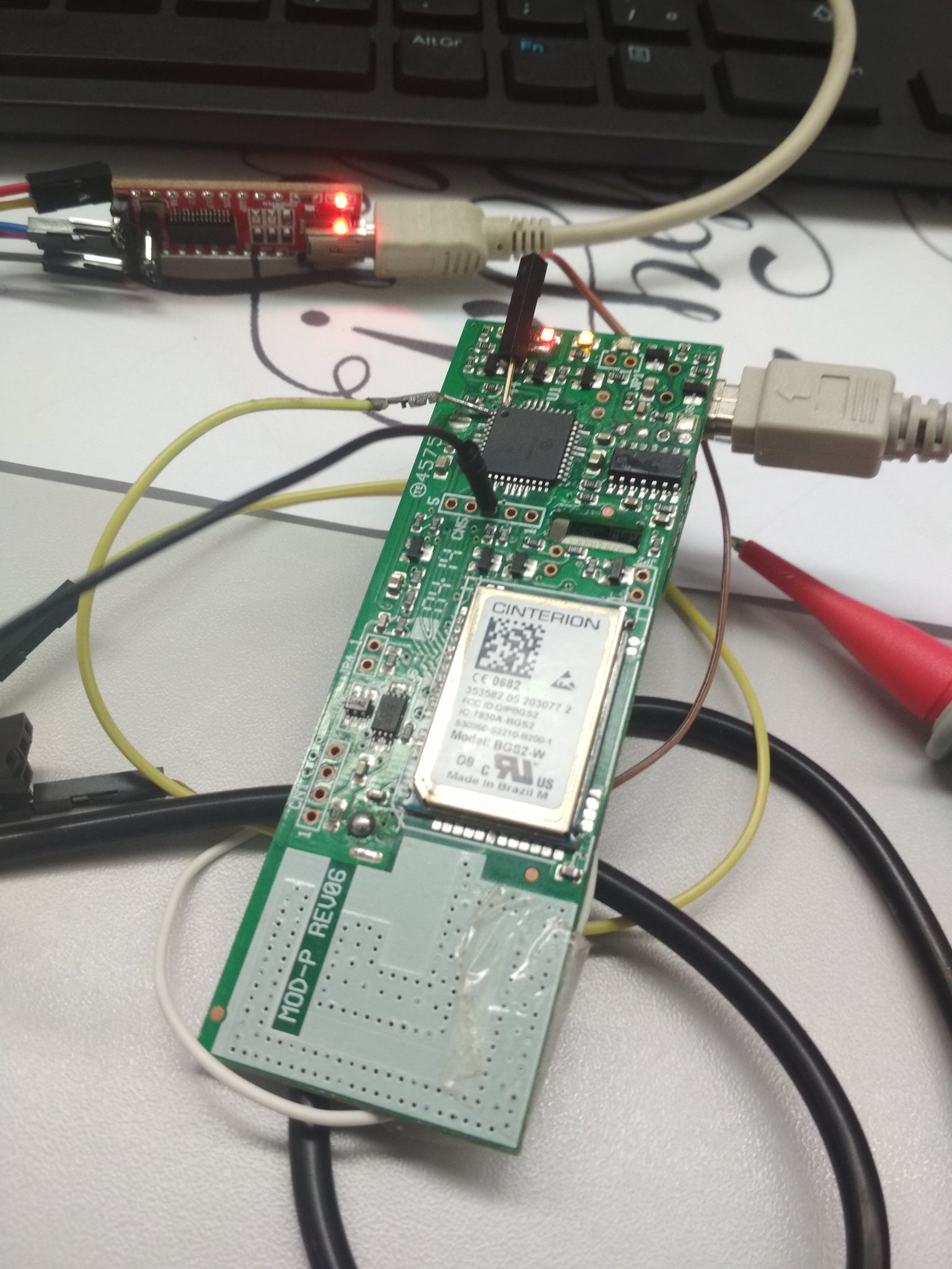
The 18650 had nothing special on it other than it being rated at 2600mAh. The GSM module was actually a BGS2-W from Cinterion, a 2G module that lacked any form of GNSS, which makes me wonder if they solely relied on the nearest GSM cell towers for triangulation and how efficient this actually is.
After removing the 18650 cell for safety reasons and seeing that the board had a Mini B USB port, I tried to hook it up to my PC whilst running watch lsusb to see if anything would happen, and… nothing happened, which was kinda disappointing but not surprising, that port was probably meant only for charging.
Since those modules are usually controlled through AT commands sent by serial from another device, I paid a little bit more attention and noticed that the board also had a PIC18F46K20, meaning that I could try to sniff the communication between them.
 |
|---|
| The poor board after a half-assed soldering job |
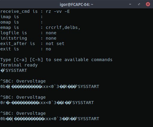
Having soldered some jumper cables into the PIC’s RX and TX pins, I connected them into my trusty FT232 USB to serial converter, plugged it to my PC with a baud rate of 9600 and powered the board through its USB port, but the only thing I got were some overvoltage messages that made no sense to me, what could be causing those? I read the PIC’s datasheet again just to make sure that it was actually 3.3v tolerant, as that’s the operating voltage of the FT232; however, it shouldn’t matter since I’m only reading data, not sending anything back to the PIC.
 |
|---|
| Overvoltage errors through serial |
Measuring the points where the battery used to me showed that the supply was fluctuating between 4.1v and 4.7v, whereas it should me at most 4.2v — the charging voltage of a lithium battery. It seems like that charging port isn’t meant to receive 5v, even though it’s a regular USB port. Weird, but what can I do? Lucky thing that I removed the battery beforehand or there would be some magic smoke escaping from it.
Knowing that, I grabbed a proper power supply and fed 3.7v to the board through the joints where the battery used to be, and finally managed to make the board talk to me.
 |
|---|
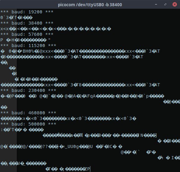
| It lives! Kinda… |
The sad part is that I couldn’t get a proper, readable output from it no matter what baud rate I set (I tried everything from 1200bps to 921600bps). As I ran out of ideas and got tired, I simply thew the board aside and gave up on it. Maybe I actually killed it when supplying the wrong voltage. But hey, at least I managed to kill off some hours of my morning.